
2.7.4. Stage V CAN bus overview
Description
The EEM4F Electronic Engine Management system contains three different CAN buses.
CAN 2 / CAN C Ancillary bus 250kbps
All the CAN actuators are present in the ancillary bus shown in figure Ancillary bus
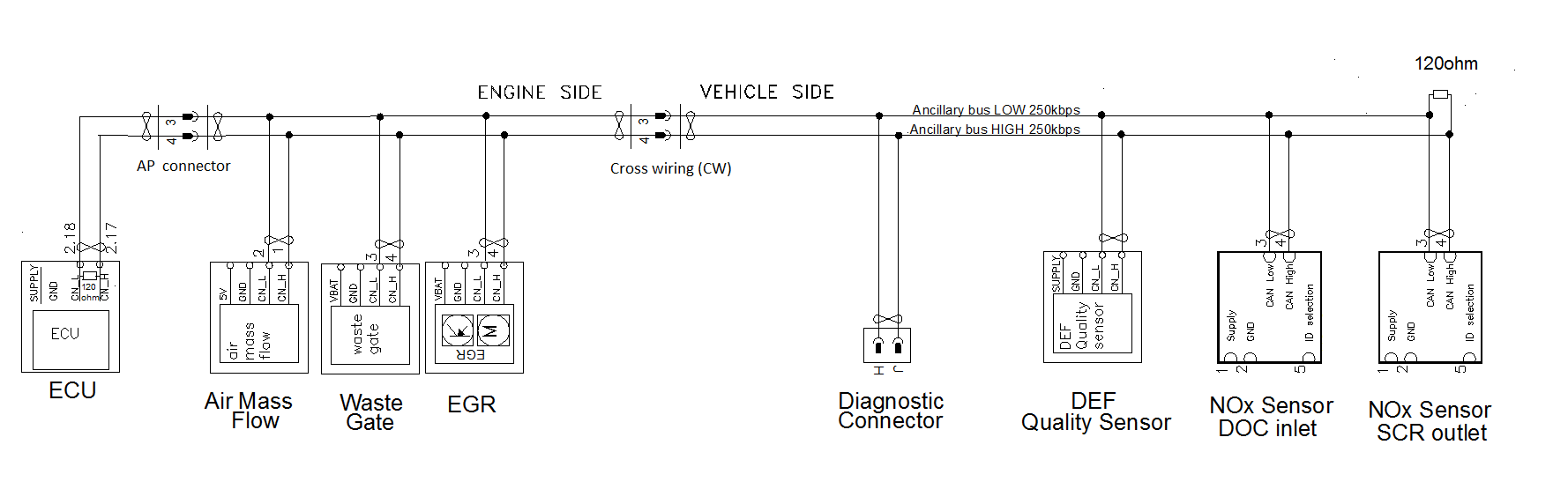
Ancillary bus
The diagnostic connector is located in the ancillary CAN bus, and the connector is in accordance with the SAE 1939 standard.CAN 0 / CAN A Powertrain bus 250kbps
The powertrain bus is for connecting the EEM4 to the vehicle’s electrical system. The bus shown in figure Powertrain bus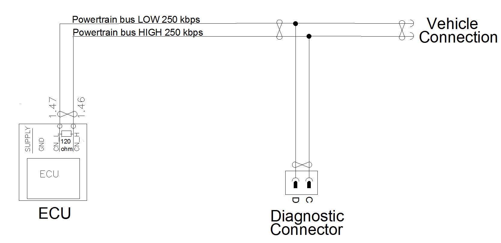
Powertrain bus